|
Chaos Oszillator designed by Uwe Schüler (Kulturgüterschuppen Dusslingen, Germany) for Circuit Control DIY Soldering Festival at Ostpol (Dresden, Germany) June 2011.
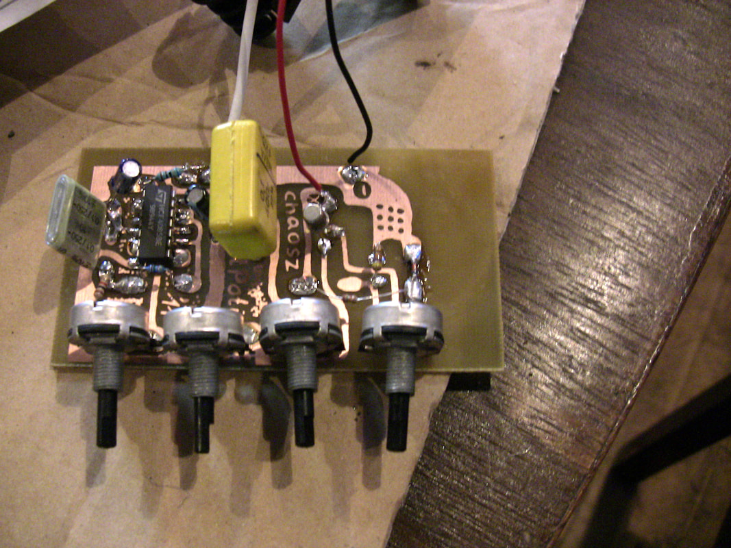
Description of the circuit by the designer A square wave generator consists of 2 CMOS inverters with variable frequency ("tone frequency") and is connected to an adjustable stabilized voltage of about 1 to 5 volts ("supply voltage control") and a variable internal resistance of 0 to 100 kOhm ("bad battery") and an adjustable filter constant ("power supply filter"). This results in feedbacks on the operating voltage, which lead to unstable and chaotic oscillations. Background "Normally, measures are taken to keep electronic circuits stable, including stabilization of the operating voltage, decoupling capacitors, and low-impedance leads to the consumption points," says Uwe Schüler, and if these rules are disregarded, then you can freak around with the most vital sounding synth you can imagine. I got experienced and jammed with the Chaosz for weeks. I soldered some more units with different modificatios. Best is the original version, the Ostpoti by Uwe. Why Chaosz sounds so great is easy to explain: Uwe has spent a lot of effort to produce a maximum unstable and dirty power supply instead of developing a clean standard oscillator. This reverse path strategy masters the studied electronics engineer Uwe Schüler perfectly and tempts the possibilities to the maximum. 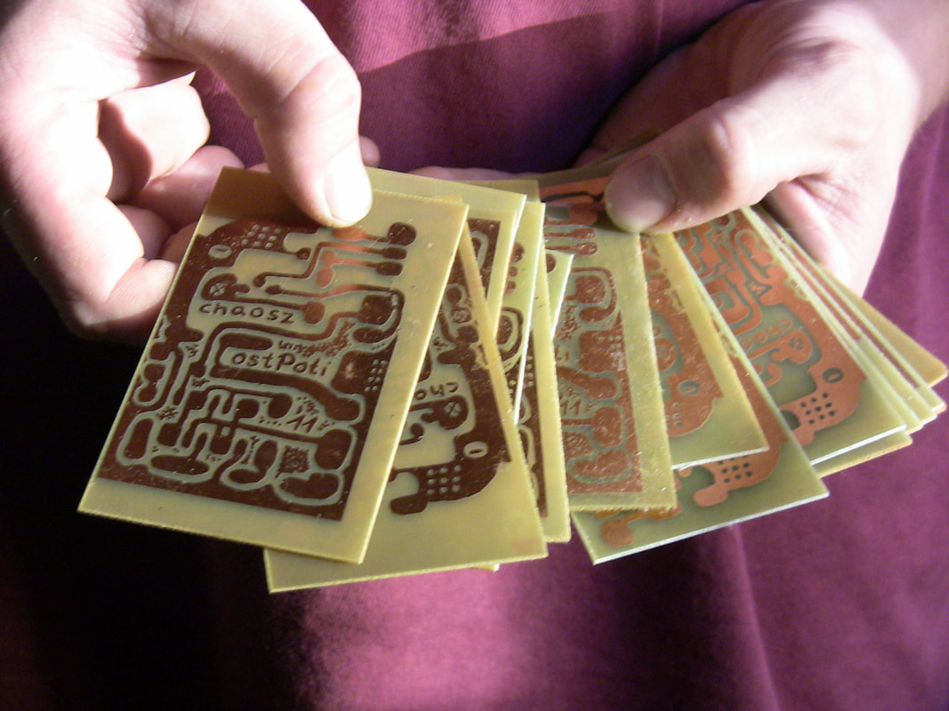
I created 90% of the sounds for "2nd Movement" ("Analoge Systeme", CD, base, 2016) with the Chaosz, also the drum sounds. Only the the polyphonic soundscapes come from another analogue synth. The live session with the Chaosz took approximately 2 hours, the editing of the sounds 2 days and the music was finished in 4 hours.
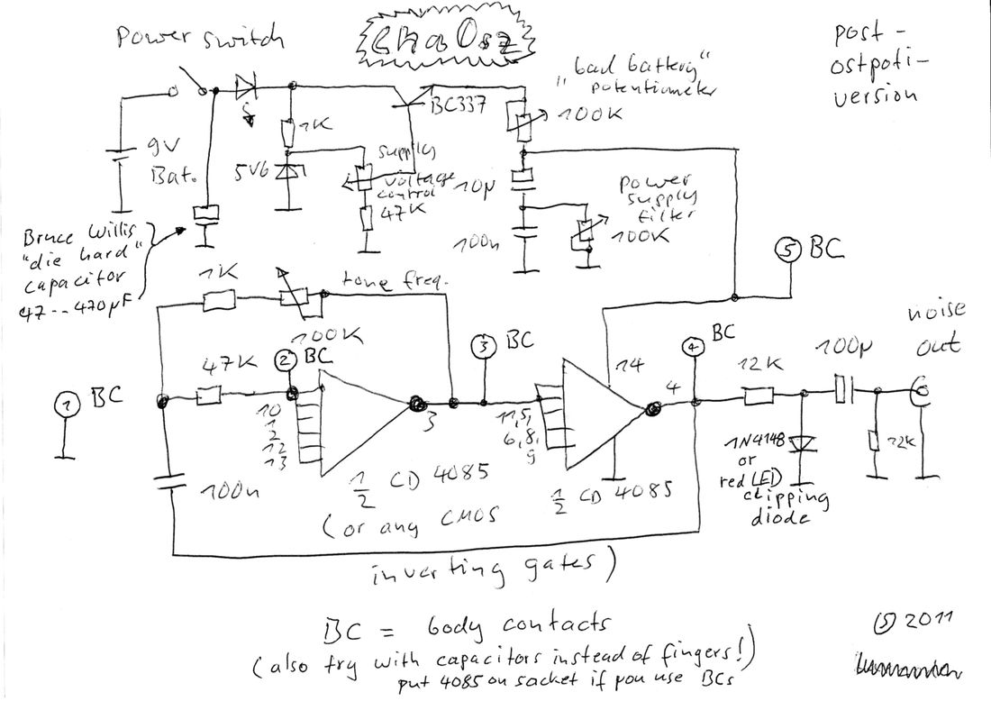
ChaOsz schematic, added to article on May 4, 2018
Wolfgang Dorninger
The series "The Circuit Controllers" continues monthly on Electronic Cottage. I will only present sound devices that I have soldered myself and of developers I know personally and appreciate as friends. Next edition: FlipFloater Delay from Claude Winterberg (Basel, Switzerland) Uwe Schüler Wolfgang Dorninger
6 Comments
4/26/2018 00:16:32
While I have some commercial synth units, I am a firm believer in low cost, diy modules, units. Low cost does not equal "junk". It would be very helpful if a schematic is included for future hardware posts. Thanks for doing this. 4/27/2018 16:31:51
Hallo Dave, 5/4/2018 03:23:58
Uwe has sent me a description in english. I will ask Hal to add the aschematics within the article. 5/4/2018 14:31:03
Thanks for the schematic and description. Hopefully I'll build one later this year.
Radek Ćwieląg
4/12/2023 12:24:14
hey. i want to bulid this. i'm quite noob in the topic. what is the second diode from powere supply section? Can use 2n3904 trasistor instead bc337?
elektrouwe
4/20/2023 02:37:15
no problem, any NPN should be ok Leave a Reply. |
Wolfgang DorningerSoldering is the new hometaping Archives
April 2020
|

 RSS Feed